Refurbishing A 1927 Switchboard, Part 1: Wiring
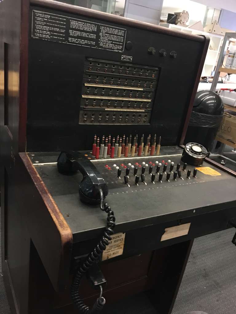
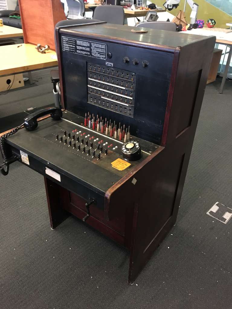
This is a manual telephone switchboard.
Specifically, it’s a Western Electric 551-A, a model originally produced in 1927. This sort of switchboard would typically be used in a hotel or small business, with an operator helping customers to connect calls within the building or to the outside world.
This particular switchboard was used at the Mead Paper Mill in Chillicothe, Ohio at least as recently as 1966. That’s like using a computer from 1977 computer today. Pretty absurd.
I’m working on a game where you play as a telephone switchboard operator. Although the piece started out using hand-fabricated custom hardware, it quickly became a project about wiring up this beauty to a modern computer.
I’ll talk more later about exactly what I’m trying to accomplish and why I’m so in love with this piece, but for now, suffice it to say that I’m interested in how we can connect with antiquated technology in a visceral and tangible way. Physically playing a game on the hardware is the biggest part of that, sure, but as I’ve come to appreciate the sheer craftsmanship of this machine, it’s become clear that sharing that with a wider audience is just as important.
This is the first in a series of exhaustive blog posts about how this switchboard works, and what I’ve done to connect it to a modern computer. I apologize if this is a bit brain-dump-y; this is being written for my future self as much as it is for you.
For this first post, I’m going to dive into the first problem we faced: figuring out how the heck this thing was wired up to begin with.
What makes a phone call?
First, some background on how a manual telephone switchboard works.
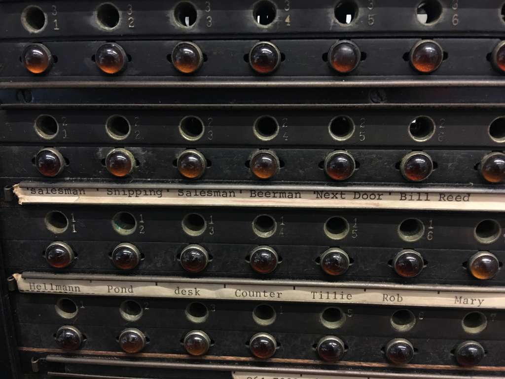
The 551-A has 50 “lines”, which for right now you can just take to mean “50 pairs of cable plugs and lights”. The top four rows are extension lines – that means each one would have been connected to a specific telephone within the building. You can still see the original labels on our switchboard – I’d like to talk to the beer man, please!
The bottom row of lines are “trunk” lines, meaning they connected to external telephone systems.
To connect a call, you’d plug a pair of matching cables in. For a cable pair, you’d use the front cable to connect to a trunk line and the rear to connect to an extension. I assume this is for technical reasons (likely only the rear cables connected to the outside), but I’m not actually sure.
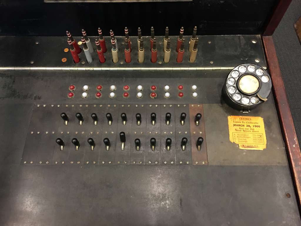
Now, see these switches and lights below the cable pairs?
Each cable has a matching light and switch. The switches are tri-state: they start neutral, and can be flipped either up or down. For reasons that will soon become clear, the two states act differently: if you toggle the switch up, it will stay in position until you move it back to the neutral position, whereas toggling the switch down is momentary.
When someone picked up their receiver to make a phone call, the light next to their plug and name label would illuminate. As the operator, you’d start by flipping one of the many switches into the up position, and then plug the corresponding cable into the correct port. Putting a switch in the “up” position connects things so that you can talk to them; after they tell you who they want to talk to, you’d flip that back down to stop listening. You could theoretically leave it up to listen in on someone’s conversation, but that was naturally considered incredibly unprofessional and unethical.
As soon as you connected to the caller, the light corresponding with the cable you used would turn on. This logic is simple: if a cable is actively connected to a caller, its light is on.
You’d then connect the second cable to the desired recipient’s plug, and flip the second cable’s switch to the down position. The down position triggers the ringer; after the recipient picks up (read: the cable’s light turns on), you’d stop ringing and let them have their conversation. When they were done, the cable lights would turn off and you could disconnect the cables at your leisure.
Making Connections
Okay, so now you’ve got a rough idea of how this thing works. How the heck is it wired up?
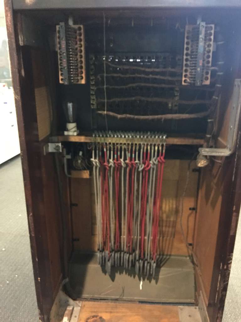
Those are cable weights at the bottom; each cable is invidually weighted so that if you drop it, it falls right back into place. So satisfying!
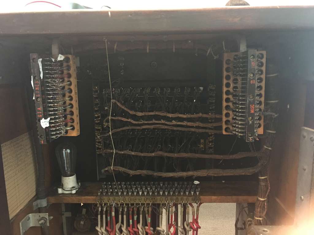
Our switchboard arrived gutted. Where a real switchboard would have had a decent amount of wiring and circuitry, we’ve instead got an impressive cut line of cable.
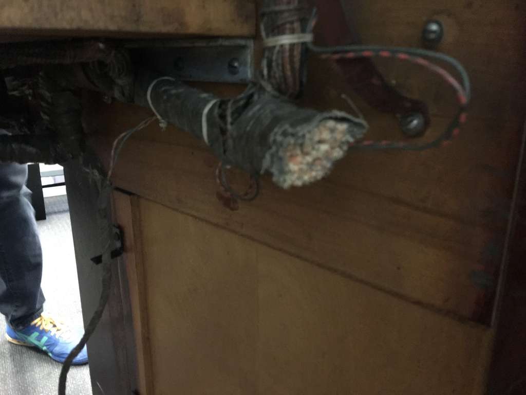
I’ve found relay diagrams of what this would have looked like, but I’m not exactly familiar with pre-silicon electrical engineering. Fortunately, that’s fine, since I don’t care about being able to use this as a functioning switchboard. I just care about the basic wiring: when I plug a cable into a port, how can I detect that they’re connected?
The cables
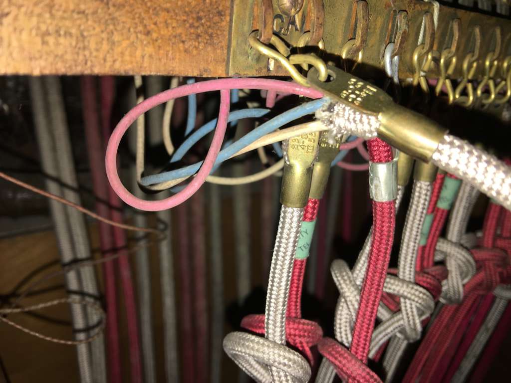
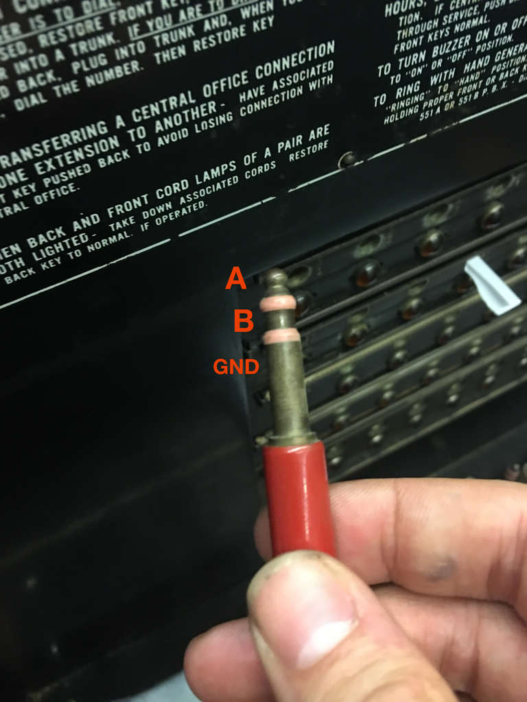
The cables are standard 1/4” stereo tip, with two rubber rings and thus 3 contact points (presumably ground and two data connections). This was simple enough to find; you can see that each weighted cable is made up of three smaller cables, each of which gets routed to a large metal contact.

The ports
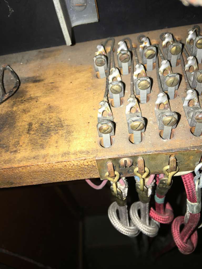
Each cable has three connections. You’d expect that to hold true for the ports they plug into as well. Curiously, though, each of the fifty cable plugs has five pins coming out of it.
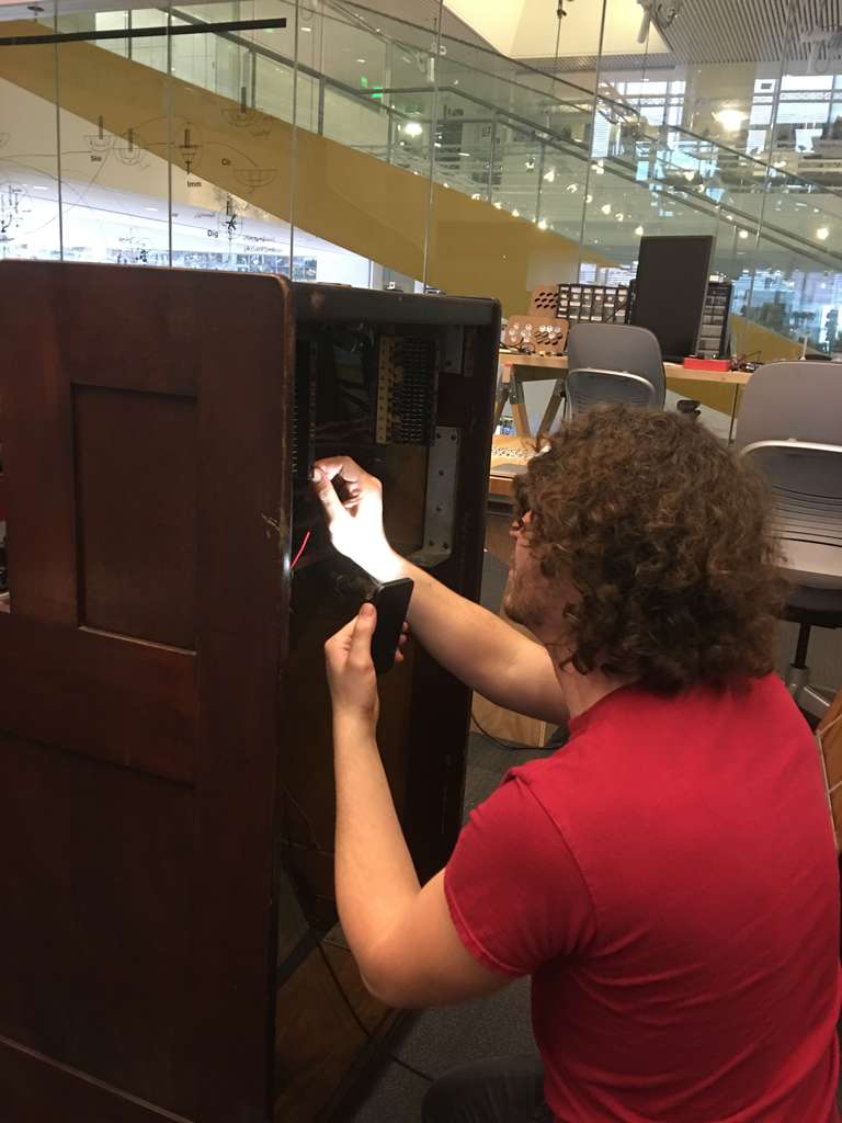
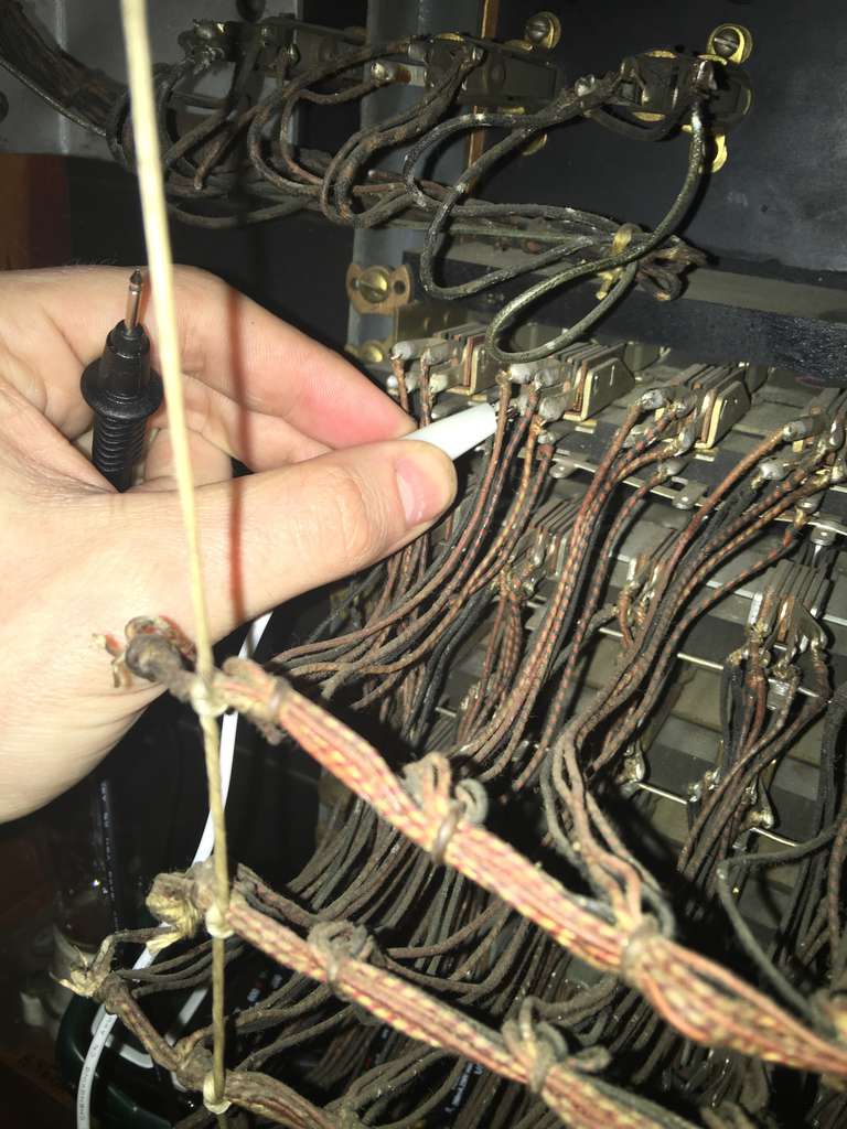
Whatever the reason for that is, figuring out which three I cared about was straight forward. I just plugged a single cable into a single port and poked around with a multimeter until I saw which connections were made. Complicating this was that the first cable I tried to use was a bit worn-down and couldn’t get a good connection, but switching cables made it a breeze. Of the five pins, three of them clearly connected to the three cable contacts.
It was obvious which of the three was ground, as it was connected across all 50 ports and 20 cables.
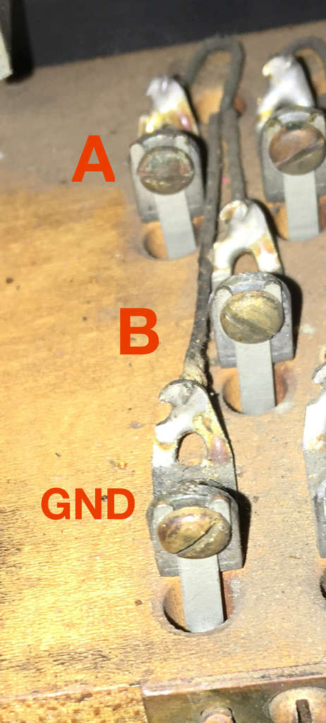
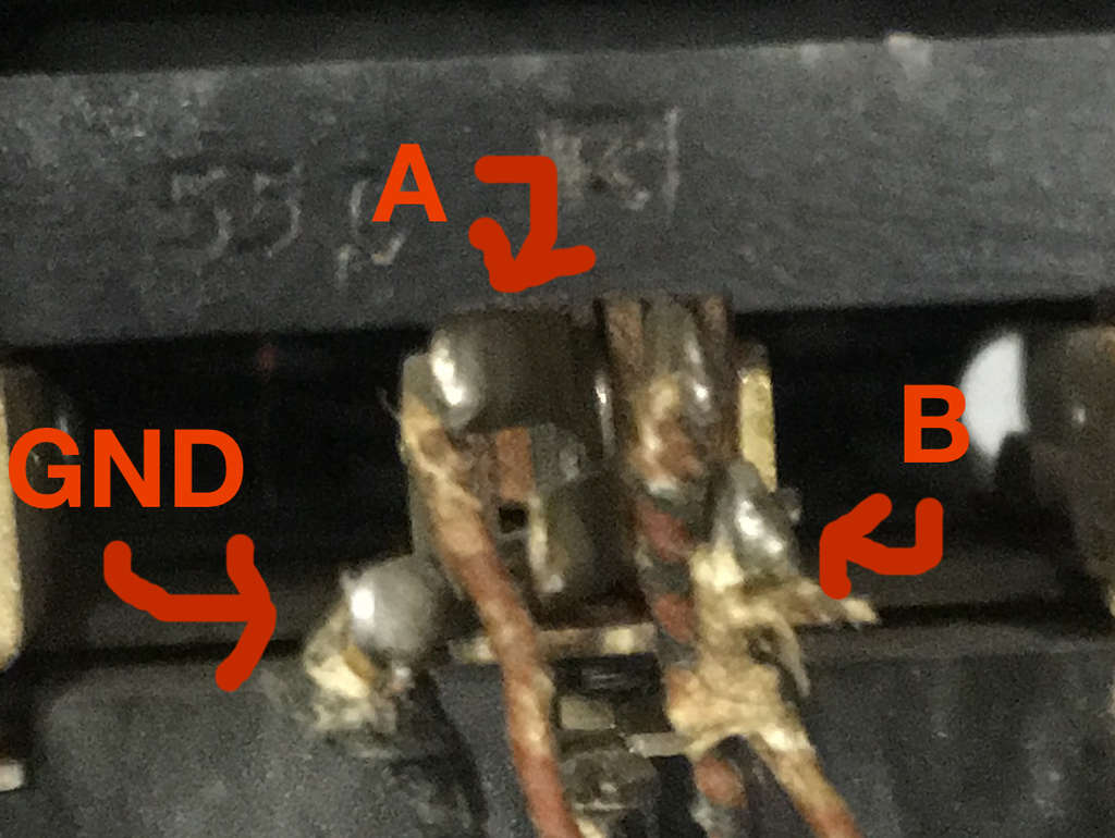
Alas, there’s a lot of wiring there. Soldering 50 connections to those pins tangled up in existing wiring didn’t seem like an ideal task. At the same time, ripping out that beautiful vintage wiring seemed like a shame. For sheer historic curiosity, sure, but also because the person who wired this up did a decent job of cable management; if I could find a way to use the existing cabling, I could easily save tens of hours in wiring.
Lo and behond, there are two big wiring blocks in front of/above the ports.
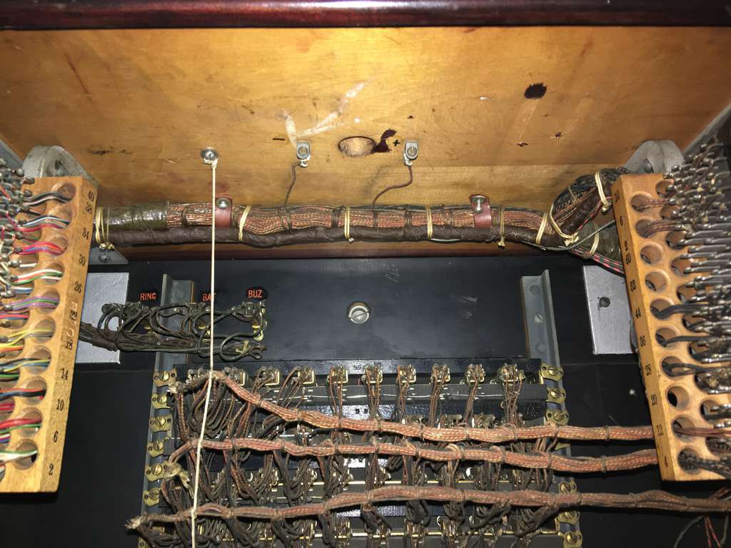
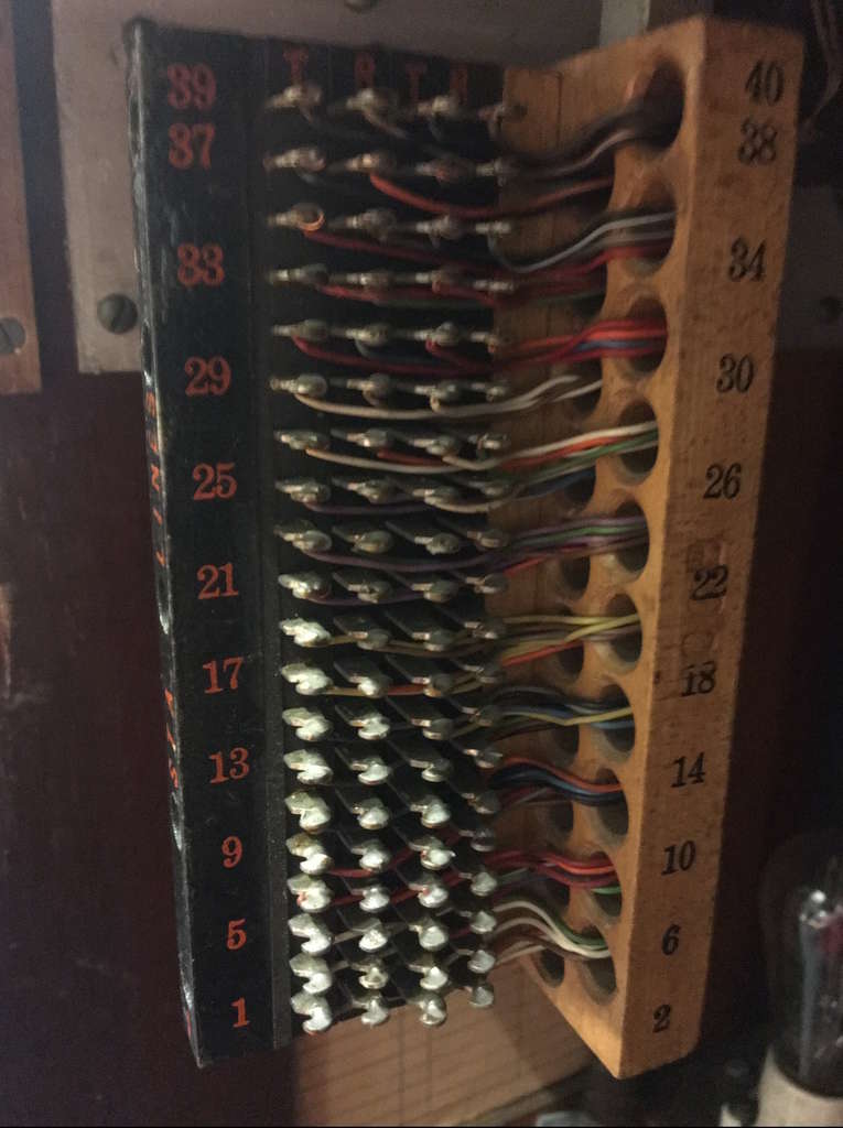
It turns out that these are in fact connected to the ports. Of the four columns, the first and third columns appear be some sort of ground: every single pin in the column is connected to the bottom-left pin of any given cable plug. The second and fourth columns are connected to the right-most pin in the plug in a predictable pattern.
For the sake of simplifying referencing things, I came up with my own numbering scheme.
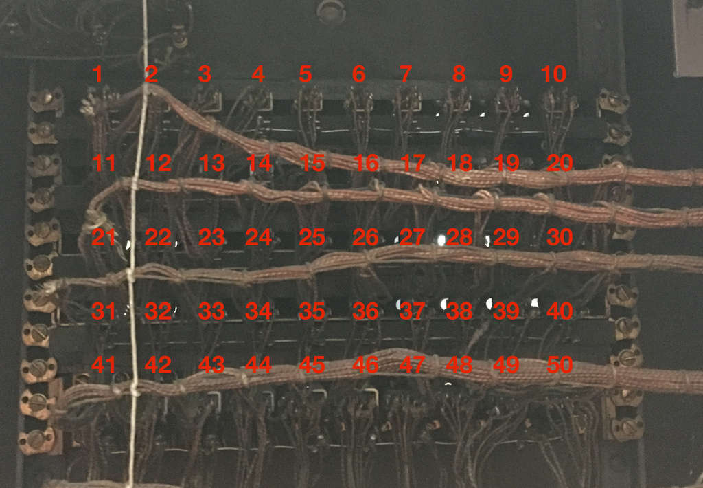
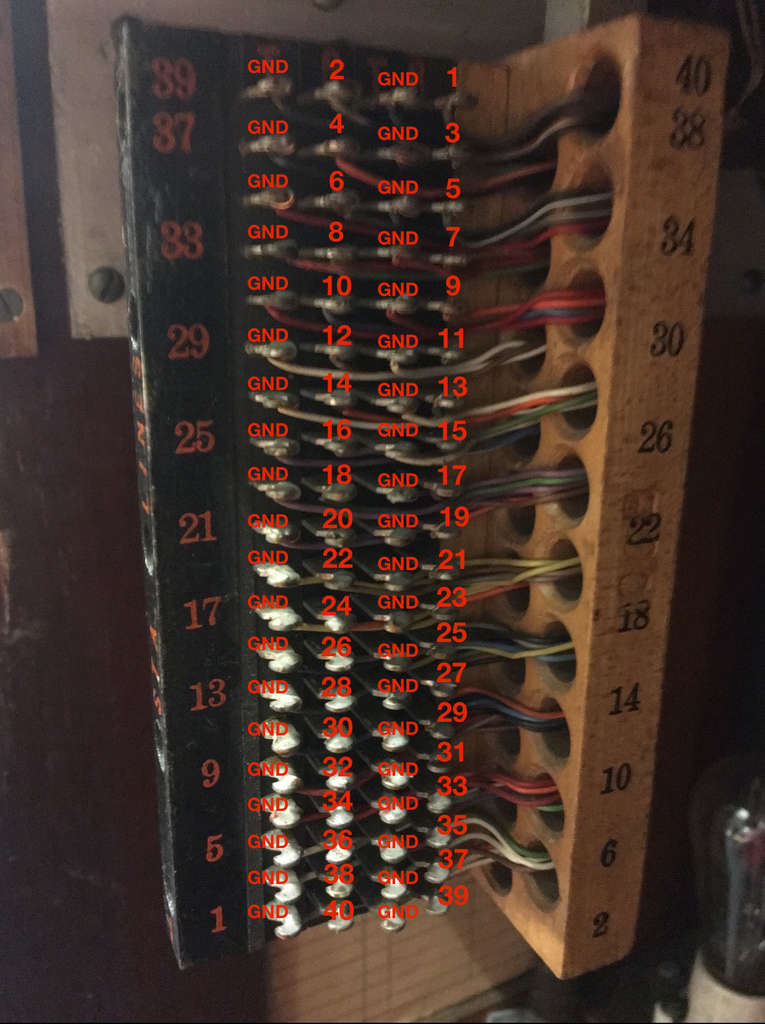
You’ll notice that even though there are 50 ports, the pin block only has room for 40 pins. This is the left pin block; the right pin block has the last 10 ports. Remember that the bottom row are the “trunk” lines for external calls; this technical distinction is likely what causes that split.
After manually confirming that all 50 were properly wired up to to the blocks, I moved onto the bulbs.
Lights
Given this switchboard model originally came out in 1927, it’s not surprising that it uses tiny incandescent bulbs rather than LEDs. Removing one of the light caps confirmed this. They’re so cute!
These were far easier to figure out than the ports. Each bulb has two pins coming out of it, one of which was clearly connected to a shared ground. Perhaps most surprisingly, most of them still worked! Most of the bulbs happily illuminated when connected to a 9v power source. Stunning. The bottom row was all burnt out, as were four other bulbs, but that’s not too shabby. While it wouldn’t be too difficult to wire up these bulbs to a modern microcontroller, we instead opted to replace them with modern LEDs. More on that later.
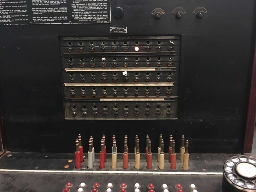
(Those little pieces of paper were me marking off which bulbs didn’t work.)
This is the point at which I recognized something frustrating: the bulb pins were also connected to the big pin blocks. At first blush, it appeared that they were on the opposite side of the block: ports on one side, bulbs on the other, in a similar arrangement. But I realized rather quickly that wasn’t the case; each bulb’s anode pin was wired directly to the plug pin I was hoping to use!
Unless I’m okay with a bulb being on every time a cable is connected (I’m not), that means I can’t use the pin blocks for wiring up the cable ports, instead soldering to the second data pin that isn’t connected to the bulbs. Needing to solder directly to the plugs is a major bummer, but being able to use the cable management scaffolding of the current wiring meant it wasn’t a total disaster (again, more on that later).
Switches
With the main panel taken care of, let’s jump down to the tabletop.

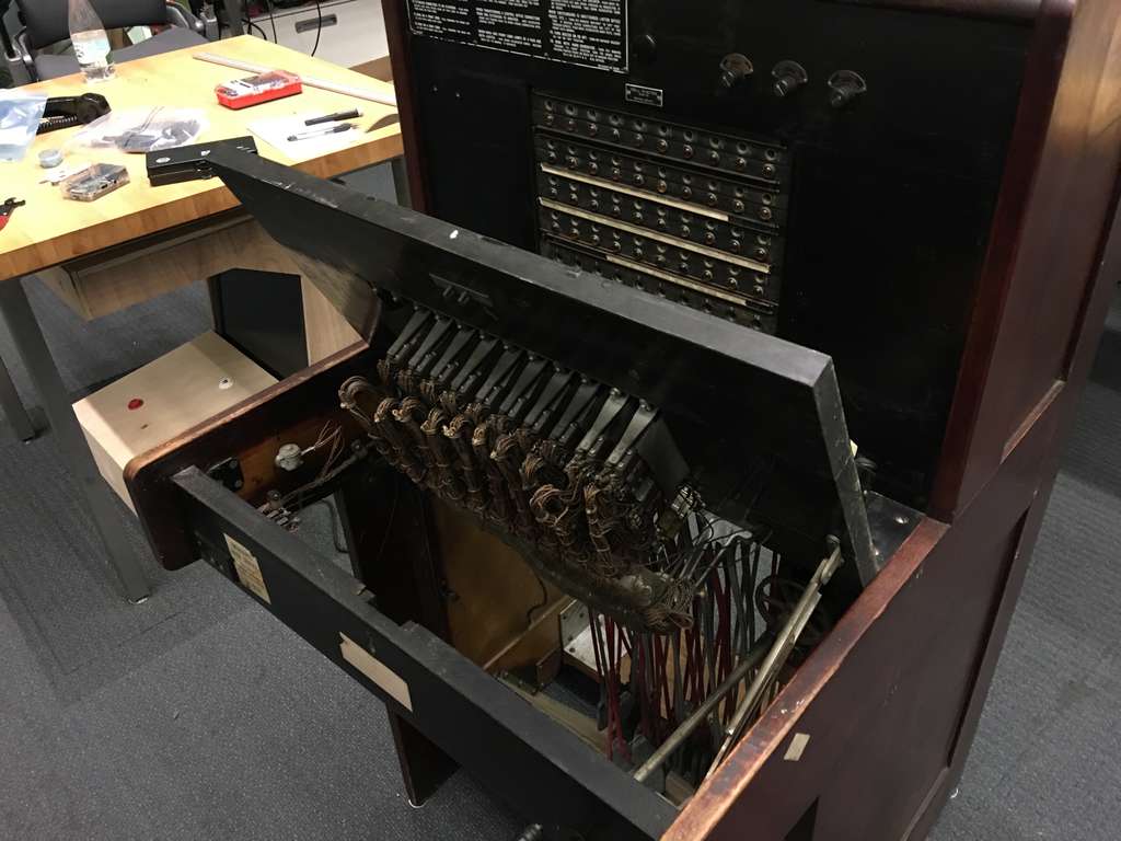
The cables aren’t an issue, since we’ve already figured them out.
The light bulbs are the same as the ones on the back, with an obvious shared ground and individual anode pin per bulb.
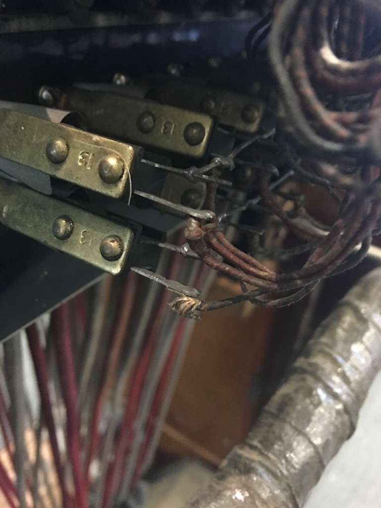
That leaves us with the switches, which are far more interesting.
Even though each is a single physical switch, the mechanical logic to determine whether the ringer is active and whether talk mode is active are two separate mechanisms, each of which exists in two places. The mechanism itself is rather beautiful.
(Look particularly at the moving plates on the left)
551-A Switchboard switch mechanism from Em Lazer-Walker on Vimeo.
The way this is wired up, it’s difficult to get a good photo of exactly what’s going on, but here you can see me poking around with a multimeter.

There’s a bit of a mystery here. Conceptually, you’d assume this is very simple: it’s a switch with a neutral state and two other possible states. You could easily represent this with only 3 pins. And yet there are two separate physical mechanisms, one for each direction.
Part of this may mechanically be to accomodate the different behavior of each direction. As described above, if you flip a switch to the talk/up position, it stays there until you physically move it back; the ringer/down position will snap back to neutral as soon as you let it go.
However, that doesn’t leave the biggest mystery. Like with the cable ports, each of these two mechanisms has way more pins than you would expect. The “ring” mechanism, which is the rear one of the two, has four pins; the “talk” mechanism in the front has five. Even weirder, each physical switch has four mechanisms in total; each switch has two talk mechanisms and two ring mechanisms, with each pair having mirrored pin layouts.
I discovered a couple of really interesting things. Unlike the cable ports, I was able to figure out what some of these mystery pins do. For the “talk” mechanism, a number of the pins are momentary switches. They’re not connected when the switch is in the neutral position, nor are they connected when the switch is in the “talk” position, but as you’re in the process of flipping from one to the other they make contact for a fraction of a second. Absolutely stunning, and makes me wonder how this fit in to the actual relay logic.
I was eventually able to figure out for both the “talk” and “ring” mechanisms which two pins I could use to reliably determine whether the switch was in the appropriate position or not, but even then I ran into yet another snag. For both rows of switches, the “ring” position had a shared ground line: of the two pins I cared about, one of them was connected to all 10 switches. This makes life easy for wiring this up, since I can just wire up my microcontroller’s ground pin to one of them, and they’ll all share it. This was also the case with the “talk” mechanism for the front row of switches.
However, it wasn’t the case for the “talk” mechanism on the rear row of switches. There was a common ground across all 10 switches, but it wasn’t one that was connected to the circuit I needed; it triggered with the momentary toggles, not the normal “it’s connected!” pin. I ended up eventually manually wiring up a shared ground, which wasn’t too hard, but this just makes me wonder even more about the original circuitry for this thing.
Next steps
Whew, what a journey! I’ve left a bunch of cool things out (the rotary dial! The buzzer! The hand-crank you’d turn to manually generate power!), but that’s more than enough for today.
Next up, I’ll talk about what an unexpected difficulty it was to merely get access to the interior of the front panel at all. Stay tuned!
If you’re interested in playing “Hello, Operator!” in person, it will be shown at the Game Developer’s Conference in San Francisco, CA from March 16-18, 2016 as part of alt.ctrl.GDC.
